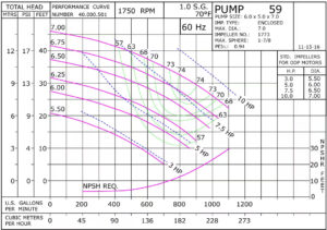
In the realm of hydraulic engineering, a pump curve holds a wealth of information that speaks volumes about a pump’s capabilities. For many aspiring engineers, deciphering the intricacies of a centrifugal pump curve might seem daunting at first. However, grasping these curves is indispensable for those involved in specifying hydronic equipment.
In this blog, we’ll delve into the components of a pump curve, more accurately termed a “pump performance curve,” and explore the reasons these elements play a crucial role in pump selection.
Primarily, it’s essential to recognize that manufacturers meticulously craft curves for each pump they produce. These curves, born from extensive hours of factory or laboratory testing, provide insights into how a pump will perform under specific conditions, aiding in the optimal selection of a pump for a given application.

Let’s highlight the main facets of a pump performance curve.
Total Head and Pump Flow Capacity: Represented on the vertical and horizontal axes, respectively, these values are critical in understanding a pump’s pressure capabilities and flow rates. The total head, measured in feet on the y-axis, signifies the pressure a pump can overcome, factoring in the total system head, encompassing elements like friction head and static head. On the x-axis, the pump flow capacity denotes the gallons per minute (gpm) a pump will deliver during operation.
Pump Efficiency Curves: Beyond assessing a pump’s capability, we consult pump curves to gauge its efficiency. Manufacturers provide efficiency information on the curves, with lines intersecting the head-capacity curves and labeled with percentages. For instance, a pump curve may reveal that a pump with an 6.75″ impeller delivers 800 gpm and a total head of 37 feet at 74% efficiency. It’s evident that efficiency varies with flow and head, and the ideal pump choice often operates slightly to the left of the Best Efficiency Point (BEP).
Impeller Size: The size or “trim” of the impeller significantly influences a pump’s performance. The pump performance curve displays the pump’s performance with various impeller sizes, enabling engineers to pinpoint not only the best pump but also the optimal impeller selection.
Brake Horsepower (BHP): Indicating the horsepower required to operate the pump at different points on the performance curve, BHP is crucial information illustrated by lines sloping downward from left to right.
Required Net Positive Suction Head (NPSHR): To operate efficiently, a pump demands a specific amount of pressure at the suction. Pump curves include the NPSH requirement for each operational point along the curve, expressed in feet of head above the performance curve.
As we explore further in subsequent posts, we’ll unravel more insights into pump curves and how they empower effective and reliable pump selections. Stay tuned for a deeper dive into this essential aspect of hydraulic engineering.
By: Nash Mohammad, B.Eng
