Plate & Frame Heat Exchangers:
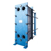
The primary purpose of heat exchangers are to transfer thermal energy from one fluid to another fluid without the mixture of the fluids; i.e. the fluids are separated. Typically this is used when one loop is connected to a boiler/chiller and another loop is connected to a heat rejection system such as an evaporative cooling tower. The concept of fluids not being mixed allows for different types of fluids to transfer thermal energy, i.e. glycol & water. Figure 1 below displays an assembled plate & frame heat exchanger.

Figure 1: Tranter Branded Plate & Frame Heat Exchanger
Below are some of the key advantages of plate heat exchangers:
- Very compact
- Very efficient
- Low maintenance & service required
- Varying demand can be accomplished
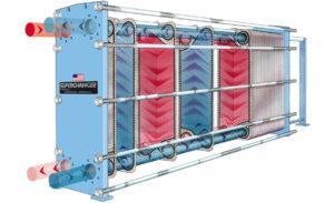
Plate & frame heat exchangers are comprised of a front & back cover which can be referred to as a frame, a plethora of plates in between as well as gaskets, and tightening bolts assembled with nuts to hold the heat exchanger together. Figure 2 below depicts the blown out assembly of this type of heat exchanger.

Figure 2: Blown out assembly of the plate & frame heat exchangers
The front covers are typically made of some form of mild steel as they are meant to be extremely strong in order to hold everything together. The nuts sit on the tightening bolts which run through the entire length of the heat exchanger which will compress the plates & gaskets together very tightly, making the heat exchanger leak proof. The plates is where the heat transfer occurs and the gaskets allow for the fluid to not leak. Larger heat exchangers will come with large supporting bars that are assembled along the top and the bottom in order to hold the frames & plates together. In smaller heat exchangers, since they are assembled with the tightening bolts only, the frame & plates can easily be removed by sliding it out.
The plates themselves are usually made of some form of steel or titanium with a groove/pattern designed and/or stamped onto them as portrayed in figure 3. These patterns are incredibly thin but strengthen the plate. They also allow for an increase of heat transfer as the surface area increases as well as creating a rough and turbulent flow.
The gaskets are typically made of a type of rubber that allows the prevention of leaks. These gaskets fit in between the plates and also are designed with the grooved pattern. These gaskets allow one type of fluid to travel through the plates/sheets but prevent other types of fluids from travelling through that sheet.

Figure 3: Zoomed in image displaying the plate & it’s grooved patterns
A key advantage of plate & frame heat exchangers is that they can be increased in size (or decreased) in order to match the demand. This is able to be completed due to the extended length of the tightening bolts. With any extra length on the tightening bolts, one may simply add on more plates that can slide along and be completely tightened with the frame & nuts. This ability of simply adding more plates is a great benefit as it allows owners to match an increase in demand without the requirement of purchasing new equipment.
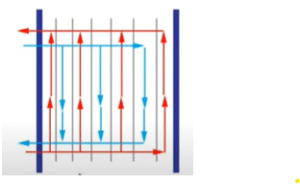
There are many methods of how the fluids travel through the heat exchanger. One of the more popular methods is the primary fluid that requires to be cooled will enter the front frame from the bottom and travel through every subsequent plate up to the top channel which will then travel outwards from the front frame again. While this occurs, the fluid which is being heated up also travels through the front frame but from the top channel this time, which travels downwards through every other plate into a channel below allowing the fluid to travel outwards from the front frame as well. Figure 4 displays this concept below.

Figure 4: Fluids method of travel through heat exchanger
The above version of the heat exchanger is the most popular/common version as it does not require any of the piping to be altered with if the heat exchanger is changed in the future (such as an increase of plates due to increase of demand). There are other versions as well where the fluid being cooled can enter from the front frame and exit through the back frame while the fluid being heated can enter through the back frame and exit through the front frame. This method however is not as practical as it requires piping to be re-worked if the heat exchanger is ever in need to be altered in the future.
The channel will only allow access of fluid being able to travel through certain plates but won’t allow it to be so through certain other plates. This is what allows the prevention of fluid mixture while still creating an efficient method of heat transfer. The key idea is that the gasket will allow fluid to pass through certain plates but not others.
Some key terminology worth nothing is that the plate & frame heat exchanger can sometimes be referred to as a gasketed plate heat exchanger of GPHE. In reference to the Tranter brand SuperChanger GPHE, the transfer typically occurs between two different waters or even from steam to a liquid.
Other key advantages not mentioned in detail are in regards to the reduced footprint which inevitably results in a cheaper cost. The GPHEs fit into 20-50% of a shell & tube heat exchanger footprint which includes the maintenance space. The GPHEs are highly versatile with hundred of plate styles, patterns & draw depths to precisely match certain application requirements.
When it comes to heat exchangers, although simple in concept, choosing the right fit in sizing and plate pattern can become a challenge. Always reach out to your local manufacturer’s representative and/or HVAC expert to discuss the best selections for your applications!
By: Nash Mohammad, B.Eng
